How to take apart your Dt366 and remove your ide flash memory
Posted: Mon Mar 30, 2009 11:12 am
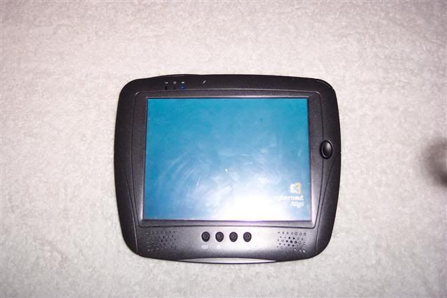
Ok so the first thing I did when I got my DT366 outside of cry about the lack of c35 apps was what every geek does. I took it apart. I figured I would take it apart again and this time make a tutorial for the rest of you .
I in advance apologize for the crappy pics my camera is a turd.
[img width=480 height=320]http://img.photobucket.com/albums/v110/ ... 0Small.jpg[/img]
Step one
Remove your external battery and eject your Cf card if you have one in . It makes it alot easier .
Step Two
Remove the two screws from the internal battery cover and remove your internal battery.
[img width=480 height=320]http://img.photobucket.com/albums/v110/ ... 4Small.jpg[/img]
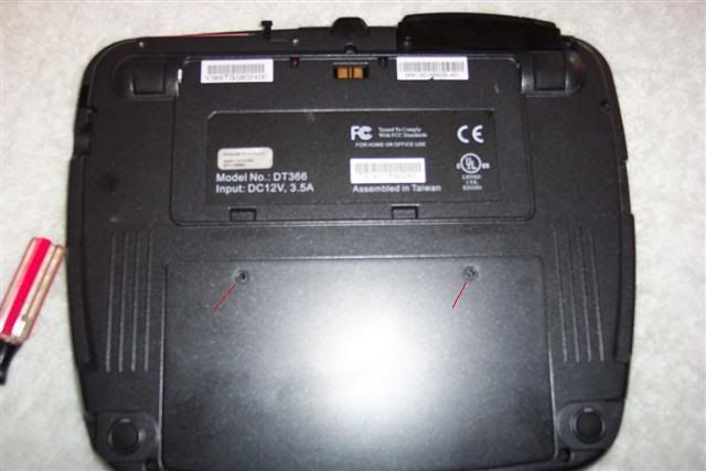
Step Three
Remove the 6 screws on the back of the unit as marked below the bottom middle one is below the white sticker.
[img width=480 height=320]http://img.photobucket.com/albums/v110/ ... 6Small.jpg[/img]
Step Four
flip your unit over and remove the front bezel . Then remove the Five screws marked below.These are holding the board and screen to the back bezel. Make sure to get the middle right one its hard to see sometimes.
You will notice all but one of these screws are long than the ones you have dealt with up to this point. Oddly the short one is the bottom right hand corner screw this will come in handy when you go to put it all back together.
[img width=480 height=320]http://img.photobucket.com/albums/v110/ ... 7Small.jpg[/img]
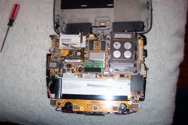
Step Five
Ok now you have to slowly and easily remove the board /screen assembly from the back bezel however donot pull it off quickly because there are two wires that connect to the back bezel. I typically do not remove these two cables I just flip the bezel up and out of the way.
and now your looking at the motherboard and all of its glory woohoo . The green rectangle in the middle is the source of all of our frustration and fury the Ide flash module. This removes simply by pulling straight up on it . iits on tight but it does come off.
[img width=480 height=320]http://img.photobucket.com/albums/v110/ ... 9Small.jpg[/img]
Here is a picture of the flash chip removed. It is hard to tell with the angle of this pic but you can see how low profile the connector is and that is s the part that bites us in the butt about using most aftermarket ide flash chips.
[img width=480 height=320]http://img.photobucket.com/albums/v110/ ... 7Small.jpg[/img]
Here is a horrid pic of the onboard IDe pins . you will notice they are the same as a standard 44 pin ide which is the same as a notebook hard drive. but they are shorter than most so they wont go far enough into most connectors to make a connection. I have a couple of low profile 44 pin ribbons on order to try and mod them to work but who knows. you should be able to hook up a notebook hd to these but this is untested.
[img width=480 height=320]http://img.photobucket.com/albums/v110/ ... 2Small.jpg[/img]
I in advance apologize for the crappy pics my camera is a turd.
[img width=480 height=320]http://img.photobucket.com/albums/v110/ ... 0Small.jpg[/img]
Step one
Remove your external battery and eject your Cf card if you have one in . It makes it alot easier .
Step Two
Remove the two screws from the internal battery cover and remove your internal battery.
[img width=480 height=320]http://img.photobucket.com/albums/v110/ ... 4Small.jpg[/img]
Step Three
Remove the 6 screws on the back of the unit as marked below the bottom middle one is below the white sticker.
[img width=480 height=320]http://img.photobucket.com/albums/v110/ ... 6Small.jpg[/img]
Step Four
flip your unit over and remove the front bezel . Then remove the Five screws marked below.These are holding the board and screen to the back bezel. Make sure to get the middle right one its hard to see sometimes.
You will notice all but one of these screws are long than the ones you have dealt with up to this point. Oddly the short one is the bottom right hand corner screw this will come in handy when you go to put it all back together.
[img width=480 height=320]http://img.photobucket.com/albums/v110/ ... 7Small.jpg[/img]
Step Five
Ok now you have to slowly and easily remove the board /screen assembly from the back bezel however donot pull it off quickly because there are two wires that connect to the back bezel. I typically do not remove these two cables I just flip the bezel up and out of the way.
and now your looking at the motherboard and all of its glory woohoo . The green rectangle in the middle is the source of all of our frustration and fury the Ide flash module. This removes simply by pulling straight up on it . iits on tight but it does come off.
[img width=480 height=320]http://img.photobucket.com/albums/v110/ ... 9Small.jpg[/img]
Here is a picture of the flash chip removed. It is hard to tell with the angle of this pic but you can see how low profile the connector is and that is s the part that bites us in the butt about using most aftermarket ide flash chips.
[img width=480 height=320]http://img.photobucket.com/albums/v110/ ... 7Small.jpg[/img]
Here is a horrid pic of the onboard IDe pins . you will notice they are the same as a standard 44 pin ide which is the same as a notebook hard drive. but they are shorter than most so they wont go far enough into most connectors to make a connection. I have a couple of low profile 44 pin ribbons on order to try and mod them to work but who knows. you should be able to hook up a notebook hd to these but this is untested.
[img width=480 height=320]http://img.photobucket.com/albums/v110/ ... 2Small.jpg[/img]